Hardware
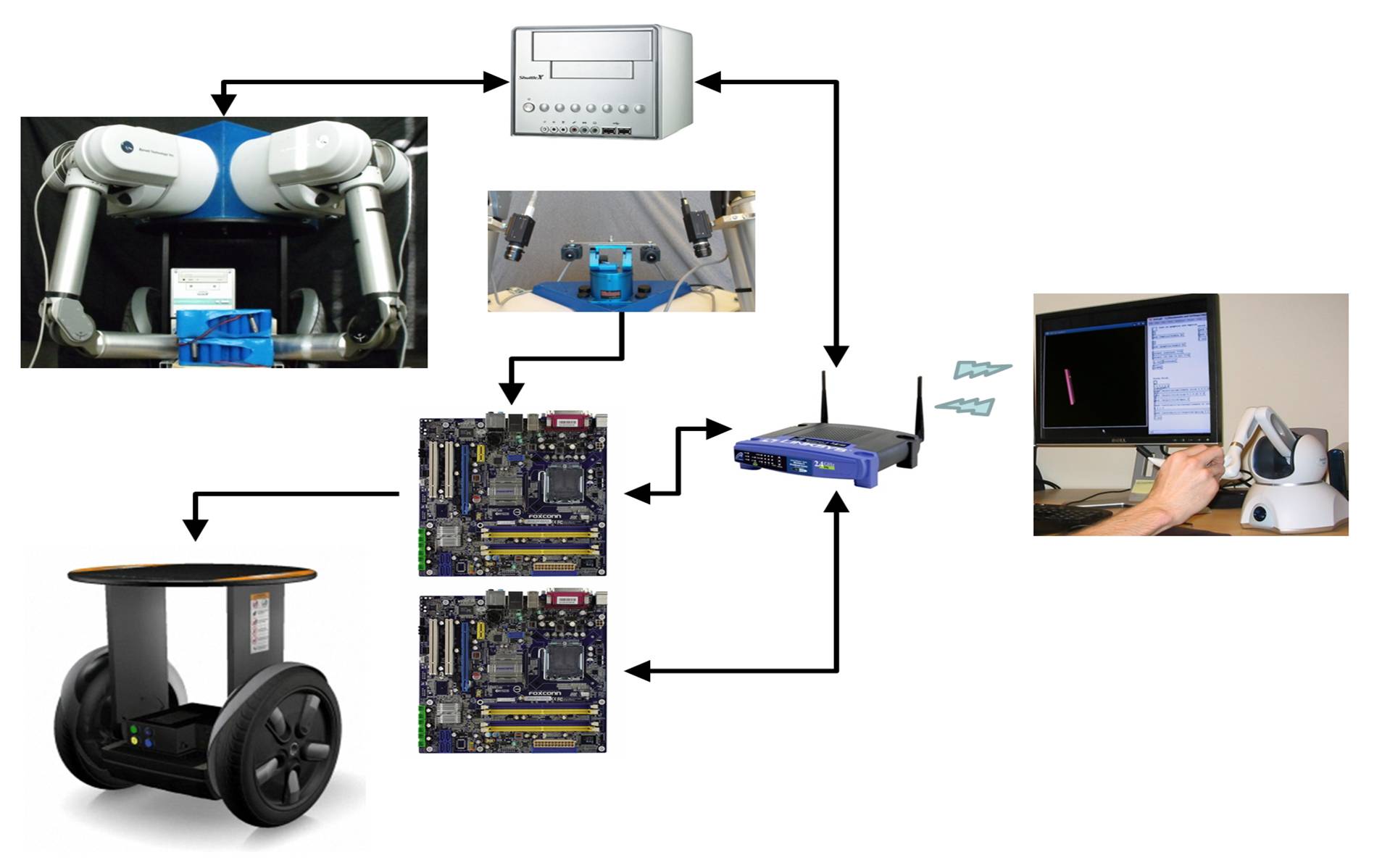
Hardware Connections Diagram
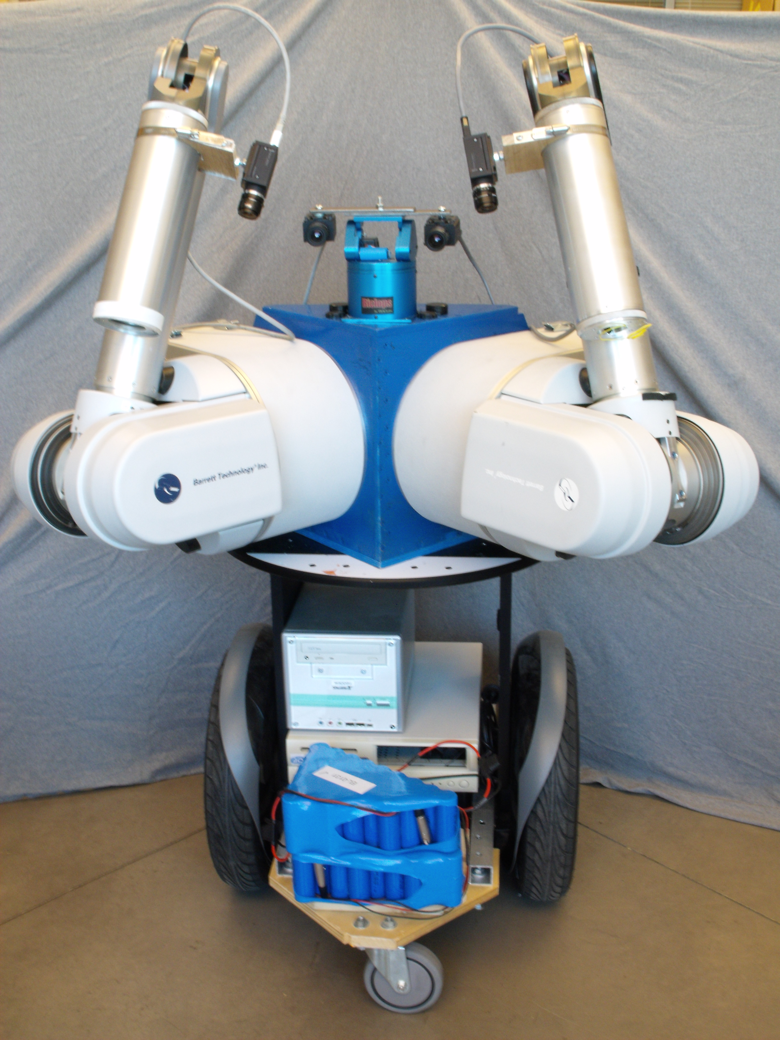
Two WAM arms atop of Segway RMP
Hardware Connections Diagram
Two WAM arms atop of Segway RMP
We designed the main power source for the robot to be a single battery bank and all the different subsystems are connected to a main power bus. The bank consists of NiCd Batteries (robust). With this configuration we avoid the need to charge several battery packs separately and also we equalize the running time of the system overall. We also considered that the PSU of each subsystem could be fed on AC or DC which enables the system also to be used with an AC common power line.
| Subsystem | Idle | Typ. Load | Peak |
| WAM 4DOF | 18W | 28W | 600W |
| WAM 7DOF | 27W | 45W | 800W |
| 2 Computers | 70W | 150W | 190W |
| Cameras | ≤ 10W | < 10W | ≤ 10W |
| Segway RMP | Integrated Battery | ||
| Total | ≤ 125W | < 250W | ~ 1600W |
We built PC workstations for the purpose of controlling the robot. These workstations gave a good power/computation ratio and provided good expandability (including new cards for different purposes). Both of the Workstations were customized with mutiple core processors. The Motherboards were selected to be small sized [µATX 9.6"x9.6"]. Each computer has an IEEE 1394b PCIe interface board to connect two PtGrey Grasshopper cameras. Currently we have another 2 computers, one PC104 and a Shuttle Zen, each controlling one of the arms. These two computers will be substituted in the near future with a single computer to make synchronization between the arms less complicated.