A house has a very simple alarm system with four sensors:
(1 week)
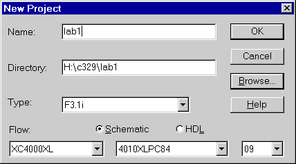
NOTE: when creating your project, the flow should be "schematic", the first drop box should be "XC4000XL", the second drop box should be "4010XLPC84", and the third drop box should be "09"
A house has a very simple alarm system with four sensors:
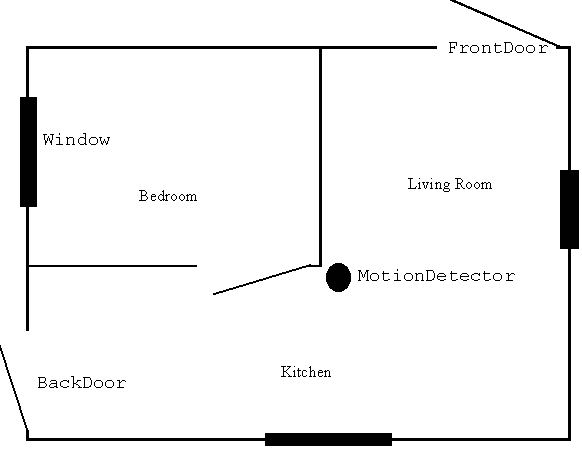
If the system is Armed and you are Away, then a signal from any of the
sensors will cause an alarm. If you are Home, then only a signal from one
of the two doors will cause an alarm. If the system is not armed, then
there will never be an alarm.
1. a. Convert the description above into a logical equation.
b. Construct a truth table for this equation. Since the complete truth table would have 26 = 64 lines, you can combine Window and MotionDetector columns into one column that is the OR of the two original columns (W or M), and you can do the same to combine the front and back doors into (F or B).
c. Draw a sketch of the circuit for this equation.
 .
Refer to the Wiring FAQ
if you have trouble. (8 min)
.
Refer to the Wiring FAQ
if you have trouble. (8 min)
3. Test your design in the simulator (simulation box on main screen) 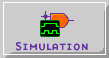 . This is called a "functional simulation" and is used to check that the logical function of the circuit is correct. Basically, this simulator acts like a truth table. You should make sure that your circuit produces the correct outputs for all possible inputs.
Fix any problems with your design that are uncovered by the simulation. Save an image of the correct waveform
for inclusion in your lab report. Refer to the Simulator
FAQ if you have trouble.
. This is called a "functional simulation" and is used to check that the logical function of the circuit is correct. Basically, this simulator acts like a truth table. You should make sure that your circuit produces the correct outputs for all possible inputs.
Fix any problems with your design that are uncovered by the simulation. Save an image of the correct waveform
for inclusion in your lab report. Refer to the Simulator
FAQ if you have trouble.
Question 1: If the alarm is armed, and you are away, how long does the functional simulator show it will take for the alarm to sound (alarm to go high) if
a. Someone opens the back door? (remember that this is a Functional simulator)
4. Connect the Input lines to the parallel port as follows:
| Signal Name | Pin Assignment | GSXPort Button (Used later in lab) |
| Window | P44 | D0 |
| FrontDoor | P45 | D1 |
| BackDoor | P46 | D2 |
| MotionDetector | P47 | D3 |
| Home/Away | P48 | D4 |
| Armed/UnArmed | P49 | D5 |
| Alarm (output) | P20 | N/A (middle segment of the LED) |
To make these connections, refer to the Wiring
FAQ(use
method 1). After you have finished this, you need to create a netlist for
your schematic. The netlist describes how the components are connected,
and is required for the software to implement your design. To create
the netlist, select "Create Netlist" from the options menu in the schematic
editor.
5. Implement the design and download to the FPGA. To implement the design,
click on the "Implementation" box in the project manager 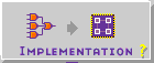 .
If it asks you if you want to update the netlist, click "Yes". On the next
popup, make sure that the device is "4010XLPC84" and the speed is "09".
.
If it asks you if you want to update the netlist, click "Yes". On the next
popup, make sure that the device is "4010XLPC84" and the speed is "09".
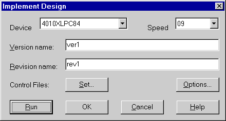
Then click "Run". Another window, the flow manager, will open as the implementation
process goes through all of it's steps. When this is done, it should tell
you that your desing was implemented successfully. Test the design in hardware
to ensure correct operation. Show the TA that your implementation works
correctly. If you have trouble with implementation you may want to check
the Wiring FAQ, or the Errors
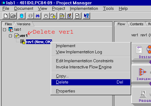
or Warnings list. If you need to make changes to your design, make sure to delete the old version, or your changes may not take effect:
You need to use the GXSLoad program to program the FPGA, and the GXSPort program to control the inputs to your ciruit. If you have trouble
with downloading to the FPGA, you might want to check out the GXSLoad
section of the XESS Tools FAQ.
6. Now, go back to the main screen and select "timing simulation" from
the verification box  . This is the same as the
functional simulator, but now that the design is implemented, it knows more
details about the physical realities of the
circuit, such as how far apart the input and output pads are, what
are the gate specifications, etc... So now, the simulator will reflect these time
requirements of your ciruit. Retest your design, and save a copy of
the waveform for inclusion in your lab report. Be sure to zoom in far
enough when you are measuring time differences. For instructions of measuring time differences, refer
to the Simulator FAQ.
. This is the same as the
functional simulator, but now that the design is implemented, it knows more
details about the physical realities of the
circuit, such as how far apart the input and output pads are, what
are the gate specifications, etc... So now, the simulator will reflect these time
requirements of your ciruit. Retest your design, and save a copy of
the waveform for inclusion in your lab report. Be sure to zoom in far
enough when you are measuring time differences. For instructions of measuring time differences, refer
to the Simulator FAQ.
Question 2: If the alarm is armed, and you are away, how long does the timing simulator show it will take for the alarm to sound (alarm to go high) if
a. Someone opens the back door?
b. Someone opens the window? (independent of opening the door)
c. If the alarm is on after (a), how long does it take for the alarm to stop if the door is closed?
Question 3: Compare and
contrast the functional simulator, the timing simulator, and testing in hardware
(what are the advantages and disadvantages of all three, especially in
comparison to each other?). When is each form of testing most and least
useful/appropriate? What important information can you gather
much more easily in each case, as opposed to trying to gather that information in another
way (if there even is another way to get the information)?
What is the value (point) of each type of testing?
7. Complete your lab writeup. Make sure to include everything required (see the lab report requirements and guidelines), including (but not limited to) your simulation waveforms, your schematic diagram and TA sign-off sheet. Also, include answers to all the questions.
Congratulations, you have completed the your first CMPUT 329 lab.
[Return to CMPUT 329 Lab Home Page]