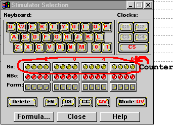

Q: How do I make signals show up in the simulator?
A: First, the simulator will only let you observe/drive nets that
have been named in the schematic. Refer to the Wiring
FAQ for instructions on naming a net. Next, you need to tell the simulator
which signals you want to observe/drive. To do this, select "Add Signals"
from the Signal menu. Double click on the input and output lines that you
want to be part of the simulation (i.e. the lines that you want
to observe (output) or drive (input)). The signals that you have selected
will have a red check mark beside them (on top of the blue waveform). When
you have selected the signals, click the close button at the bottom left.
The signals will now appear in the list on the left side of the simulator.
Q: How do I drive inputs?
A: You need to add simulators. Choose "Add Simulators" from the signal menu. This will bring up the Simulators window.

To assign a simulator to a signal, first select the signal, then click on the desired simulator. Note that more than one signal can be driven by the same simulator. For example, suppose that you wanted the keyboard key "r" to drive the "reset" signal:
1. with the simulators window open, select reset from the list of signals (gets blue highlight)
2. click on the "r" key in the picture of the keyboard on the simulator
window. There will now be an "r" in the yellow column to the right of the
signal names. Pressing the "r" key will toggle the state of the "reset"
signal. Note that the signal starts in an "unknown" state. Thus,
before you start simulating, press the "r" key to put the signal in a known
state.
Q: Is there an easy way to simulate all the possible values of several signals? (Is there a way to simulate a clock?)
A: Use the binary counter. It is the row of yellow dots (label on the
left is "Bc:"). To assign a bit of the counter to a signal, first click
on the signal in the list on the left side of the main simulator display
(gets blue highlight). Then click on the right-most yellow dot. B0 will
appear in the yellow column just left of the signal. Repeat, assigning
the signals to the bits of the counter moving leftward. The counter automatically
increments every 10ns, which is the default time step. Thus, each step
will give a new combination of signal values until all the combinations
are exhausted. A clock can be simulated the same way - B0 will give the
fastest clock, and higher order bits will give slower clocks.
Q: How do I move forward in time (progress with simulation)? Can I change how much I move forward in time?

A: In the top button bar, the second dropdown list has amount of time to step by. It should be set to 10ns. To the right of that is a button with two shoeprints diagonally across it. That is the step button. Each time you click that button, time will go forward by the amount in the dropdown list. To change the amount of time you step by, simply change the amount in the dropdown list.
Q: How do I measure the amount of time between two events in the simulation?
A: Right-click on the simulation area (where the waveforms are
drawn). From the context menu, selectMeasurements->Measurements On. The cursor
in the simulation area will now change to a span measurement icon. You
can only measure between events (changes in signal values). To make a measurement,
first click on the triggering event (i.e. the signal that changes
first, that causes the other signal to change (left-most)). Then, click
on the responding event (where the other signal changes (right-most)).
Green lines will drop down from the events and connect horizontally just
beneath the responding signal. The time difference will be marked in red
just above the horizontal green line, with units. If you do not see the
time, then you need to zoom in so that there is enough room between the
two events to display the time. You can mark as many times as you wish.
To delete measurements, right click again, and choose one of the delete
options from the Measurements menu.
Q: How do I zoom in/out?
A: Use these buttons:

Q: How do I save an Image of my waveform for my report?
A: To save an image of the waveform from your simulation, first zoom so that the whole thing fits on the screen, then select "copy waveform" from the waveform menu. Next, open paint and paste the image in. Crop the image so that it does not include blank space at the bottom and right side. In paint, cropping can be done by dragging the handles on the sides and corners of the image area inward (the handles are grey, and hard to see, but they are there). (Remember to save the bmp!)
Q: How do I open paint?
A: From the Start Menu (click the Start button in the bottom left of the screen on the task bar), select Programs -> Accessories -> Paint.
[Return to CMPUT 329 Lab Home Page]