A constraints file uses specific syntax to describe the assignments of inputs to pins. For example, to assign pin #88 to the signal labelled "clk" in the top level of your design, you would write
For a bus of signals (such as those going to LEDs), you must set the pin location for each signal. For example, for a bus labelled LED, you would add the following to your .ucf file:
net LED<1> loc = p39;
...
Note: The signal (or net) names that you use in the constraints file must match the case of those used in your design, or the implementation tools will not be able to meet the constraint.
The ISE constraints editor is a feature that gives you a graphical interface for assigning constraints to your design. This editor then automatically generates the above .ucf file for you.
To use the constraints editor, you must first have created a constraints file (although it need not have any information in it), and add it to your project. To add a blank constraints file, you can simply add a Project -> New Source and select the "Implementation Constraints File", entitled <projname>.ucf. To use this constraints file, first select your top-level file in the hierarchy tree. Next, in the ISE design flow window on the bottom left, you can double click the constraints editing option. The window that opens will have many options, but by selecting the Ports tab, you can bring up the following window:
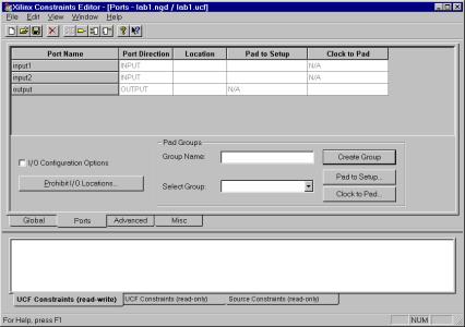
This window now allows you to assign pins to the top level inputs and outputs of your design. Simply fill in the Location field of each input with the assigned pin. The window at the bottom displays how these assignments are reflected in your .ucf file. Once you have finished entering the assignments, simply save and implement your design.